Monday 31 October 2011

Activating a View Port in Revit

Here's how you activate a view Port in Revit
  1. Open the sheet.
  2. In the drawing area, select a view on the sheet.

Tip: If views on the sheet overlap, press Tab until the correct view highlights. Watch the status bar for the description of the viewport.

  1. Click Modify Viewports tab - Viewport panel - Activate View.

Revit Architecture displays the sheet title block and its contents in halftone. Only the contents of the active view display normally. You can now edit the view as desired. You can zoom in to the drawing area to see the elements more clearly.

  1. Modify the view as desired.

For example, you can do the following:

    • Add dimensions.
    • Add text notes.
    • Pan the view within its viewport, so that only a portion of the view is visible on the sheet. The crop region for the view does not move. Right-click the activated view, and click Pan Active View. Drag the cursor to pan the view.
    • Change the scale of the view. On the View Control Bar, for Scale, select the desired scale.

To deactivate the view on the sheet, click View tab - Sheet Composition panel Deactivate.


Friday 28 October 2011

Adding Fonts in Revit

Currently, Revit supports all installed True Type®, ANSI fonts. If these fonts are loaded you computer, you can use them in Revit.

To load fonts:

1.                     On the Windows Control Panel, click Fonts.

2.                     Select File - Install New Font.

3.                     Install the font on the system.

For some True Type fonts, there are some problems with text output into PDF files in Revit PDF Writer. The source of problem is the older style TrueType fonts. Since the introduction of TrueType technology, Adobe and Microsoft have made additional improvements and now support OpenType fonts. For more information, read the article about OpenType fonts.
Tests indicate that newer OpenType fonts work better with Revit PDF Writer. If you look in the Windows Fonts directory, you will see older TrueType font files shown with the letter "T." OpenType fonts are shown with "O." Most of fonts installed by Windows are now OpenType

Wednesday 26 October 2011

Scaling Views on a Sheet

When placing a view onto a sheet the view may not be the appropriate size.

There are a couple tools that you can use to manipulate views after you have dropped them onto your sheet.
1 When placing “Regular” views (other than 3D views) or selecting a view already on a sheet the Modify Viewports Tab will appear. Under this Tab you have a couple tools to assist you.
     On the Option Bar you can rotate the view 90deg.


You can Crop the size of the view to fit better on your sheet. Below is the dialog box that opens when you select this tool.


This tool allows you to activate the view (much like the viewport in AutoCAD) where you can work on the model through the viewport. To De-activate the view right click and you will see the option to De-activate the view.

 You can also change the Element Properties of the View on your sheet  by selecting the view and selecting the Element Properties.
3D views on a sheet are a little more tricky, you still have the “Rotation on Sheet” tool on the Options bar as well as the “Activate View” tool but you’ll notice that you no longer have access to the Crop tool.

Here you will have to set up the view how you like it in the actual view, display, crop region, scale etc. Remember if you want to save the view so you don’t inadvertently change it save the view and name it. Alternately create a camera view and use this, camera views are perspective views and you cannot change the scale.

Monday 24 October 2011

Room Bounding and Revit Linked Files

Here is a quick tip....

we liked in the shell of a building into our model as we were working on the interior design.
We could not create room spaces where the room was bound by the Revit Linked model.

If you select the Revit link under the type Properties you'll find the check box for Room bounding is unchecked by default. Check this box and you'll be able to now use the linked Revit model objects as room bounding...


I personally think that this should be on by default not off..... 

Friday 21 October 2011

Creating a Parkade in Revit

I was looking at the best option for building a parkade slab with multiple ramps with multiple slopes and here is what I came up with.

 1.       Creating a floor (slab) and adding Sub Element points which I can then specify the heights of these points.

2.       Create individual floors and add a Slope Arrow where I can then specify the desired slope.


Here is a break down of each method.

·         I typically start with a sketch diagram calculating the slopes and heights I need for each level and slope of ramps required.


·         Now draw a detailed outline of your parkade, remember to draw separate lines where two slopes butt up against each other.


·         After you have sketched your floor and finished pick the your slab and under the Shape Editing panel add additional points where the slope break lines occur. You may want to draw some sketch lines as references prior to adding the points.
 
·         From the diagram you made you can now input the height values for each Sub Element point until you have completed changing the heights for all Sub Element points.


You should end up with something like this:

You can then embellish your model with barrier walls, vehicles and directional arrows, parking stall lines etc...

A couple disadvantages using this method are if your level changes you will have to edit each sloped floor element you created independently.

You can achieve the same results using the slope tool when creating separate floors, however I find this harder to manipulate overall if your levels change...

Wednesday 19 October 2011

Common Revit Keyboard Commands

I have updated my list of common Revit Keyboard commands.
These are the most common used commands with Keyboard shortcuts.

Here it is...


·         AL = Align

·         CM = Place Component

·         CO = Copy

·         DI = Dimension

·         DL = Detail Line

·         DM = Draw Mirror point

·         DR = Door

·         DE = Delete

·         ER = Editing Request

·         EW = Edit Witness Lines

·         GR = Grid

·         GP = Create Group                                     

·         LI = Model Lines

·         LW = Line work

·         MA = Match Properties

·         MD = Modify

·         MM = Mirror (along reference plane)

·         MO = Modify

·         MV = Move

·         OF = Offset

·         PN = Pin

·         PP = Properties

·         RE = Resize (Scale)

·         RH = Reveal Hidden Elements

·         RM = Room

·         RO = Rotate

·         RT = Room Tag

·         RL = Reload Latest

·         SE = Snap End

·         SL = Split Elements

·         SM = Snap Mid

·         SO = Snap Off

·         SP = Snap Perpendicular

·         SQ = Snap Quadrant

·         SS = Turn off overide

·         SU = Sun Settings

·         SX = Snap Points

·         SZ = Close

·         TG = Tag

·         TL = Thin Line

·         TR = Trim (Fillet, Trim Extend)

·         TX = Text

·         UP = Un-Pin

·         UN = Project Units

·         VG = Visibility Graphics

·         WA = Wall

·         WN = Window

·         WT = Window Tile

·         ZA = Zoom All (Used with tiled windows)

·         ZF = Zoom Fit

·         CTRL +S = Save

·         CTRL+O = Open

·         CTRL+Z = Undo

·         CTRL+Y = Y Redo


CTRL = to add to selection

SHIFT = to subtract from selection or force horizontal or vertical

TAB = Cycle through selection or snaps

Monday 17 October 2011

Dimensioning in Revit

Here is a quick tip when Dimensioning.

Typically we'll start the dimension tool and pick point to point to complete our string of dimensions.

This method is using the Pick "Individual References" mode where we select each point we want to dimension.  

If we take time to look at the options bar and what we can select you'll see we also have the option to select the entire wall.


Here when we choose the "Entire Wall" the Options become active and we can select what references the Auto Dimension will refer too.


However I do find that the dimension selection may need to be edited after placement of the auto dimension but it is still a quick way of dimensioning.

You can edit what dimensions refer too by using the Edit Witness Line tool (EW) after selecting the dimension string you want to edit.


Activate this tool and then select the reference dimension you want to remove or add, then click in the blank space to finish.

Friday 14 October 2011

Temporary Dimension Size

Do you find that the Temporary Dimensions in Revit are too small and too hard to see clearly.

Whenever I teach Revit or do a presentation I will adjust the size of the temporary Dimensions so that can be viewed clearly by the audiance or class on the overhead projector.

In Revit 2011 you use to have to manipulate the revit.ini file, a daunting task if your not comfortable working under the hood (bonnet) of Revit.

In Revit 2012 it's a lot easier.


Under the Options button on the Application menue, on the Graphics Tab at the bottom you'll find where you can edit the size of the Temporary Dimensions....a lot easier than changing the revit.ini file!!!


If you need information on how to change the Temporary Dimensions on 2011 let me know and I'll post instructions.


Wednesday 12 October 2011

Temporary Dimensions

As you create or select geometry, Revit Architecture displays temporary dimensions around the component. This is useful for placing the component in the proper place.

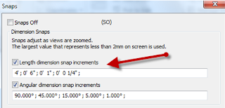
Temporary dimensions are created to the nearest perpendicular component and increment by the set value. For example, if you set the snap to 6 cm, the dimension increments in values of 6 cm as you move the component to place it.


After you place a component, Revit Architecture displays the temporary dimensions. When you place another component, the temporary dimensions for the previous component no longer display. To view the temporary dimensions of a component, click Modify and select the component. Remember, the temporary dimensions are to the nearest component, so the dimensions you see may be different from the original temporary dimensions. If there are dimensions you want displayed at all times, create permanent dimensions.

You can modify temporary dimensions to reference the components you want by moving the witness lines.

You can also specify the display and placement of temporary dimensions.

You can specify the display and placement of temporary dimensions in the design.
You can set temporary dimensions to:

·         measure from wall centerlines, wall faces, center of core, or core faces
·         measure from door and window centerlines or door and window openings
 

To specify temporary dimension settings:

1.         Click Manage tab > Settings panel > Additional Settings drop-down > Temporary Dimensions.
2.         From the Temporary Dimension Properties dialog, select the appropriate settings.
3.            Click OK.

Monday 10 October 2011

Title Block Parameters

A while ago I had to create a custom title block that had some unique parameters, both shared and independant to each sheet.

Here's how I did it.

Technical Solutions  There are two methods to use shared parameters in a project:

Method 1 Instance - To allow each Title Block parameter to vary, select Drawing Sheets under Categories in the steps below. This method is ideal for labels that will display data that varies from sheet to sheet.

Method 2 Type - To allow each Title Block parameter to utilize the same shared parameter content, select Project Information under Categories in the steps below. This will add a field to Settings > Project Information to provide easy access to the contents. This method is ideal for labels that should display the same data from sheet to sheet.

To use shared parameters from title block labels in a Revit project, follow these steps:

Create the label and add a parameter:

  1. In the Title Block family, add a new label. 
  2. Click Label > Add Parameter. 
  3. Specify the shared parameter name and settings. 
  4. Once the parameter has been created, you can add it to the Label Parameters section by clicking the Add Parameter(s) to Label button.
  5. Click the Load into Project button to load the Title Block family into the project.

Link the shared parameter from the title block family to the Revit project:

  1. In the Revit project, click Settings menu > Project Parameters.
  2. Click the Add button.
  3. Choose Shared Parameter and then click Select. Choose the title block shared parameter.
  4. Under the Parameter Data menu, choose the category to group the Parameter under. 
  5. Set the Parameter as Instance.
  6. Under Categories, select Drawing Sheets if you are using Method 1 above. For Method 2 above, select Project Information.

Once linked to the project, all shared parameters in the title block should appear blue. This allows you to enter data directly into the label. If a label appears as a red question mark, it has not yet been linked to a project parameter using the above procedure.