Wednesday, 30 November 2011

Arrowheads

Want to create a new Arrowhead style, here's how.

On the Manage Tab select Additional Settings.
Scroll down and you'll find the Arrowheads icon.


This will open up the Type Properties for the Arrowhead System Family.
Here you can now duplicate the Type to create a new style.

Through the type Properties you can now select a new Arrow Style from the drop down list.
Depending on which style you pick you can then check the tick box to fill the arrow head and also change the Arrow Width Angle to stipulate how wide you want the arrow to look and also manage the Tick Size.

These parameters will become active according to the Arrow style you select.


Monday, 28 November 2011

Preparing to Share Your Model

Office standards for preparing our Architectural Model to share with (Revit) Consultants.
Here are the steps for when you are sharing the Revit Model.


1.       Save a copy of the file to the appropriate dated folder in the email directory. If your working off a Central File you will need to "Detatch From Central " by checking the "Detatch From Central " check box on the Open dialog box. Then save the file in the appropriate directory. Detatch and Preserve the Worksets, this way whoever you send the file too will be able to manage our worksets.

2.       Go to your standard 3D view then delete all the other views including all the Floor views, Reflected Ceiling views, Elevations, detail views sheets... etc... delete all the views except your 3D view you are in (duh!). delete the Legends and Schedules. We are just sending our model so they can bring it in to base their information on, they dont need sheets and details etc.

3.       Use the Manage Links tool to remove any Linked files (CAD, Revit, etc).

4.       Purge, Purge, Purge... I typically do this three times to ensure you got everything.

5.       Save and close the file, if you look at the file size now you'll notice that it's considerably smaller.
 
Your Done! File may now even be small enough to email!

Friday, 25 November 2011

Reusing Details - CAD and Revit

Drawn some totally awesome Revit details and want to reuse them?

Or do you have a library of great AutoCAD details that you want to use in your Revit Projects.

Here are some tips on how to get the results you want when transferring from AutoCAD and saving your Revit details.

If you have a detail in CAD you want to reuse in Revit here's how I typically do it.

1) Open the detail in ACAD, if it's part of a group of other details in a file w-block it out so it's on it's own.

2) Explode it! I know we hate to explode things in ACAD but Revit doesn't like some types of hatch and this makes it easier to deal with in Revit.

3) Change everything to Layer "0". You may have to go through each group of items after selecting everything and then under the properties pick each group and change the layer to 0.

I do this so Revit wont bring in all the layers from this drawing, I don't need those, I just need the linework etc... don't worry if the line colours change or not, I typically tweak them once they are in Revit anyway.

4) I delete any leaders from the text, I do this because I typically re-write the text anyway. I do this once again so I don't bring in miscellaneous text styles into Revit that I dont want. Also if your text is single line text and not multiline text you will want to re-write it in Revit anyway so it'll be easier to manage.

5) Purge (at least twice) Audit and save your CAD detail.
Here is an example:


6) Open Revit and start a new project based on no template.
I typically save this project for future use for bringing in other CAD details.


7) Create a new drafting view, name the view and specify the scale for the detail.


8) Import your CAD detail.
Change the Colours to Black and White. Layers to Visible, auto detect Units and Center to Center for positioning.


9) BLOW IT UP!
Explode the view. I then re-write the text and add leaders where applicable, change line weights to suit and add any other information, hatches, detail etc as required.
Check your spelling.... ;-)


10) Right click on the view name in the Project Browser and select Save to New File, it should be at the bottom of the dialog box. Save the file in your Revit Detail directory.

NOTE: If you have drawn a detail in your Revit Project already follow step 10 and you can export the view out into your library for future use.

11) Open your Revit project where you want your new Revit detail to reside.
Under the Insert Tab select the drop down under the Insert from File Icon and select Insert Views from File.
This will then import the detail into your project which you can then refer your Callout too.
Wednesday, 23 November 2011

AU Virtual 2011 - The Power of the Possible

If you are unable to attend Autodesk University this year you can sign up for Virtual AU....

This online event delivers on-demand technical classes on the newest releases of Autodesk products and the latest trends and challenges facing the design industry.

AU is a great event for keeping up to date on what's new with Autodesk software as well as networking, attending informative sessions, workshops etc...

Virtual AU is free for AU members. There are 250 classes in a variety of languages covering a wide range of topics.

I've been going to AU for over 5 years now and always bring back a ton of information that I refer too quite often. I also access the AU Archive library of past classes that are available on line as well, it's a great resource!

So if you cant attend AU in person sign up for Virtual AU.
Here is some info and a link to the web site:

AU Virtual is free to all AU members. Select from 250 classes in English, Spanish, and Portuguese on a wide range of topics. Plus you can network with other virtual attendees, watch key AU 2011 Las Vegas presentations and insider videos, and visit online exhibits—right from your desktop.

AU Virtual previews are scheduled for mid-November. Join us online November 15 for technical and certification preparation classes—especially helpful if you plan to take a free certification exam at AU in Las Vegas. Then join us online November 29–30 for AU Virtual 2011.

Monday, 21 November 2011

Re-Arranging Views on a Sheet

Aghhhhh!!!!!

I have all my details in order on my sheet but I now have to add another detail and it needs to be in the middle of my sequence...!

Unfortunately there is no easy way to re-arrange views on a sheet and change the numbering sequence...
(It's on my AUGI wish list for the next version)

You have two options to resolve this issue:

 1) Delete all the views and re-place them on the sheet. (remember to write down the sequence so you dont screw it up).

 2) Select the last detail and in the properties you can change the detail number.


 If your inserting a new detail on your sheet (for example the new detail you want to be number 4), you'll have to change the number of following details (4,5,6,7,8 and 9 etc) to the next digit up (5,6,7,8,9 and 10). This way you'll be able to change your new detail to the number location you want it to be (4 in this case).

If you already added the new view before re-number the existing view you'll have to give the new view a unique number as it will have automatically added the next number in the sequence which is what you'll probably want to make your last detail.... All very confusing!

Good Luck!

Friday, 18 November 2011

Dimensioning Secrets Part 3

When dimensioning to the center of openings you can add a center line symbol and also change the line type and tick mark. On the properties of the Dimension Style you can manipulate the type of centerline symbol to use as well as the line pattern and even the type of tick mark used for center dimensions.


These changes will only apply when dimensioning to the center of objects.


Also under the dimension properties you can manipulate the how the dimension text is placed and how it is read.
Here you have a number of options for text placement.


Other properties that are worth pointing out are the Dimension Line Snap Distance where you can specify the distance between dimensions when stacking  dimensions.


Witness Line Control you can specify the gap from the object to the leader line or Fixed to Dimension Line like so...

Wednesday, 16 November 2011

Dimensioning Secrets Part 2

When dimensioning your model you have a few options for string type.
Continuous, Baseline and Ordinate.

These types allow you to represent the dimensions in different ways such as:

Continuous: Allows you to create a string of dimensions places consecutively one after another.
This is typically how we dimension for Architectural projects.

Baseline: Baseline dimensioning is when you start at a base point and separate dimension strings are created (automatically spaced evenly). I typically see baseline dimensioning in fabrication where you can place a tape measure at one end and mark off the distances as you go.

Ordinate: Ordinate dimensioning is similar to baseline dimensioning but instead of separate dimension strings it is one continuous string of dimensions with the dimension text places next to the leader dimensioning the object.

Monday, 14 November 2011

Dimensioning Secrets Part 1

Here is a series about Dimensioning and the dimension tools available in Revit...

Dimensioning in Revit is quite a powerful tool, there are a number of tips and tricks that will help you dimension your project.

You can convert you Temporary Dimensions into Permanent Dimensions by clicking on the little dimension icon.


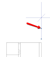
The grip at the base of the Dimension leader line controls the distance away from the object your dimensioning.


The second grip located midway along the leader line controls what you are dimensioning too. You can either drag this grip to what you want to dimension (such as another object) or if you click on the grip it will toggle through the options Center of Wall - Exterior Face of Wall - Inside Face of Wall.


Below the dimension text you'll see a padlock icon.
When selected this will Lock the dimension.

This will set the dimension distance you are so it will not change, however you can still move the object (in this case a wall) and it will move both objects (both walls at once).

Don't get this mixed up with Pinning an object which will hold it in place, locking the dimension will fix the distance but not the location, for example you can lock the dimensions of partition walls butting into an exterior wall but still be able to move the exterior wall location.

Too add or subtract dimensions to create a String of Dimensions pick the dimension and select the Edit Witness Lines tool then continuo the objects you want to dimension too.

Remember to click in the blank space to finish the dimension.

Friday, 11 November 2011

Sloped Walls in Revit

When wanting to create a sloped wall in Revit you can just change the angle of the wall by trying to rotate it.... unfortunately this doesn't work.

What you have to do is either create a mass element at the slope you want and use the convert face to wall tool. Or use the in place family tool and select the Model In Place tool and pick wall.

Now placing a door or window in this sloped wall can be challenging... unfortunately when you place a "normal" door and window it will be vertical and cut a vertical opening in your sloped wall.

What you'll have to do here is create a new window family that is based by Face.

I'll post more about this with screen shots at a latter date to explain better.

Wednesday, 9 November 2011

When to create an In-Place Family

Here are some guide lines for when and when not to create an in-place family.

When to create a Component Family

  • If there is any possibility that you'll use the family again in another project.
  • If you want to schedule specific parameters of the family.
  • If your using it in other locations throughout the project.
  • If you need to be able to "flex" the component.
 
When to create a In-place Family

  • If it's a unique component specific to the project.
  • an unusual form or shape that will only be used once or will remain the same throughout the project.
  • you don't need to schedule it.
Ummmm..... that's it!

Chances are you'll need to use it again and it's a good way to build up your component library.

Remember don't over complicate your model or your family. If you don't need the parameters or the detail in the component done include it.

The simpler these components the faster and smaller your model will be and you'll be happier.

Yes those fancy families do look impressive but so does a Lamborghini but they're a little impractical when taking the kids to the soccer field...get a Mini-Van !!


Monday, 7 November 2011

Customizing Project View Organization in the Project Browser

You can sort views and sheets in the Project Browser using any of the property values for the view or sheet. For example, the following image shows views in the Project Browser organized by discipline, then by phase, and then by view type. The top level of the Views branch also shows the name of the sort group currently applied (in this case, Discipline).
In addition to sorting views, you can also limit the views that display in the Project Browser by applying a filter. This is useful when you have a project with a large number of views or sheets, and you only want to view a specific set in the Project Browser.

The properties that you can choose from when creating a sort group or applying a filter to the Project Browser include project parameters and shared parameters. 

By default, the Project Browser displays all views (by view type) and all sheets (by sheet number and sheet name).


Sorting Views or Sheets in the Project Browser

1.       Click View tab > Windows panel > User Interface drop-down > Browser Organization.

2.       In the Browser Organization dialog, click the Views tab to apply a sort to project views, or click the Sheets tab to apply a sort to sheets.

3.       Select a sort group.

To view the properties of an existing sort group, select it, and click Edit.

4.       Click Apply, then click OK.


Creating a Project Browser Sort Group

1.      Click View tab > Windows panel > User Interface drop-down > Browser Organization.

2.      In the Browser Organization dialog, click the Views tab to create a sort group for project views, or click the Sheets tab to create a sort group for sheets.

3.      Click New.

4.      Enter a name for the sort group, and click OK.

5.      In the Browser Organization Properties dialog, click the Folders tab.

6.      For the first Group By list, select the view or sheet property to group by.

Note: Values for the selected property must be defined for each view or sheet for the sort to work correctly. To edit view or sheet properties, in the Project Browser, right-click the view or sheet name, and select Properties.

1.       If you want only the first few characters of the property value to be considered, select Leading characters, and specify a value.

2.       Optionally, select 2 additional groupings.

3.       In the Sort By list, select the order for views or sheets to display in the lowest level grouping, and select ascending or descending order.

4.       Click OK.


Editing a Project Browser Sort Group


1.       Click View tab > Windows panel > User Interface drop-down > Browser Organization.

2.       In the Browser Organization dialog, click the Views tab to edit a sort group for project views, or click the Sheets tab to edit a sort group for sheets.

3.       Select a sort group.

4.       To rename the sort group, click Rename.

5.       To edit the sort group properties, click Edit. In the Browser Organization Properties dialog, make the necessary changes.

6.       Click OK.

Adding a Filter to a Project Browser Sort Group

1.       Click View tab > Windows panel > User Interface drop-down > Browser Organization.

2.       In the Browser Organization dialog, click the Views tab to apply a filter to project views, or click the Sheets tab to apply a filter to sheets.

3.       Select a sort group, and click Edit.

4.       In the Browser Organization Properties dialog, click the Filters tab.

5.       Select the following:

a.  The view or sheet property as the filter.

b.  The filter operator.

c.  The filter operator value.

For example, to show only those project views associated with Level 1, you can create a filter by Associated Level, Equal to, Level 1.

6.       Optionally, add 2 additional filters.

7.       Click OK.


Editing a Project Browser Filter

1.       Click View tab > Windows panel > User Interface drop-down > Browser Organization.

2.       In the Browser Organization dialog, click the Views tab to edit a filter that is in a project views sort group, or click the Sheets tab to edit a filter that is in a sheets sort group.

3.       Select a sort group, and click Edit.

4.       In the Browser Organization Properties dialog, click the Filters tab.

5.       Make the necessary changes, and click OK.

Tuesday, 1 November 2011

Revit Jedi !!


A friend of mine recently referred to himself as a Inventor Jedi Master or Sith Lord but I much prefer Jedi Master as he is a wizz with Inventor.....

So that got me thinking about REVIT JEDI MASTER !!

Love it !!


Something like this....


Or more likely this. ;-)